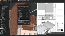
FreeCAD BIM development news - June 2018

Hi all,

Time for a new update on the development of BIM tools for FreeCAD. There is some exciting new stuff, most of it are things that I've been working for some time, that are now ready. As always, a big thank you to everybody who helped me this month through Patreon or Liberapay! We are very close to meet our first goal on Patreon. We would actually already be there if we sum up both platofrms, so next month I'll lower the goal accordingly and declare it achieved and set everything up accordingly!

So here go the new stuff of this month:

The video

This month's video is a presentation of the new BIM workbench, so in next videos we'll use it instead of Arch. As always, your comments are highly welcome (here or directly in youtube comments).

You will remember last time that I told you about the impressive series of FreeCAD-related videos made by Regis, you might also be interested in this other very nice series about BIM and open-source, with a very large part dedicated to FreeCAD, made by Nirbhay, another well-known member of the FreeCAD community. We begin to have pretty decent FreeCAD BIM learning material!

BuildingPart

The BuildingPart object I have been working on during the last months is finally ready and is part of the Arch workbench already. It is meant to replace the Arch Floor tool. For the time being, the Floor button is still there in Arch, but it already produces a BuildingPart object with its IFC role set to "Building Storey".

The BuildingPart object is still based on a classical FreeCAD Group object. I played a lot with the idea of using an App::Part instead, because it looked interesting because of its ability to automatically move its contents when you move it, and also that you can make it "active" and automatically add contents to it.

However, I discovered that it was relatively easy to reimplement these two features in another object, and also met some particularities that made me decide against using the App::Part:

  1. The App::Part only allows its children to be part of this App::Part. They cannot belong to any other. This, summed with another particularity, which is that all descendents of an App::Part also become its direct children, makes it impossible to use, for example, a same profile to build two columns placed in two different App::Parts, since the profile will become a direct child of the App::Part. This is not of big importance when designing, for example, mechanical parts, but is very common in BIM.

  2. When you add objects to an App::Part, then move the App::Part, the Placements of the objects don't change. Only their visual appearance gets moved. So if you build a column on the ground floor, then move its containing App::Part 3 meters above, the internal coordinates of the column still indicate the ground floor. And when you remove the column from the App::Part, it pops back to its original location on the ground. This is all "fixable" of course, there are methods in place to obtain the "summed up" placement of the column + its App::Part, and you can add code when removing the column from its Part to deal with the change of location, but this all seemed to me like trying to patch up something that's not really made for that use case.

    For part design workflows, this is exactly what you want: Draw your elements at (0,0), then add the to the Part, then move the Part around. If you remove elements from the Part, you want them back to (0,0). You want their internal coordinates to reflect that. In BIM workflows, I think we prefer all our elements to have real-world coordinates. Tell me in the comments if you have a different opinion!

So the BuildingPart is basically a Group, like the old Arch Floor. But with a lot of enhancements:

  • It can display a "mark" in the 3D view that shows the origin point and optionally the label and level (its z coordinate) . If you move the BuildingPart in Z direction, the level updates. You can give an artificial offset value, so for example if the offset value is 700, but your level is at z = 30, the displayed level will be 730. This is useful to work with geographic coordinates and elevations. You can also select the BuildingPart by its mark in the 3D view.

  • It can be made "active" by double-clicking it, like an App::Part. When a BuildingPart is active, all new objects will be added to it automatically, like the App Part or PartDesign Body.

  • When moved/rotated, all its children that either have no "Move With Host" property, or have it turned on, will move/rotate together.

  • When moving an object out of a BuildingPart, it will keep its current position, not "pop back" to its original position (different from App::Part)

  • It can be cloned. Internally, the BuildingPart stored a Shape, which is a compound of all its direct children. This shape is used by the clone, also keeping individual face colors. This shape is also stored on disk when saving the file, I think you'll be able to guess where we're heading for next

  • It can take any IFC type, like other Arch objects. The idea behind the BuildingPart is not only to serve as a Floor/Level/Storey, but to group BIM elements in any other possibly useful way in a replicatable manner. One obvious use would be to make a typical storey of a tower, then replicate it for the other floors, but we can also think of other replicatable things like a toilet stall, a wikihouse component, etc.

  • It can set the height of included walls and structures automatically. The Arch Floor could do that already. If a height value is set for a BuildingPart, any wall or structure inside it, that has its Height value set to zero, will adopt the BuildingPart height.

  • It defines a working plane automatically. When double-clicking a working plane, in the tree view or the BIM views manager, the working plane will be placed on the XY plane of the BuildingPart. Later on, I'll also implement the same functions that the Draft WP proxy has, which is to be also able to restore a view angle, and show/hide other objects.

    So the idea here is that you would be able, for example, to double-click a BuildingPart which represents a level of a building, and set yourself automatically in top view above this level, hide all other levels, and set the working plane to the floor plane of this level, just like if you were working in a 2D plan. When deactivating that level, you would have everything turned back on, and pop back to the view you were at before activating.

    But I found it safer to go step by step, and let people play a bit with the BuildingPart first, before implementing more stuff.

Blender importer

This is another big thing I have been working on for many months. It stayed a long time on hold because we were waiting for FreeCAD to reach a good Python3 compatibility. This is now done thanks to the hard work of several FreeCAD developers, specifically looo and Werner (and a bit of myself too). The issue there is that Blender only uses Python3 while FreeCAD was still not fully ported to it, but Python2 and 3 modules are incompatible with each other.

The code of the importer currently lives in a gist, but as soon as I get some remaining issues fixed, I'll submit it as an official Blender addon.

You can already use the importer, it is pretty stable already, but you'll need to get your hands on (or compile yourself) a version of FreeCAD compiled with the same Python version you use in Blender. The minor version number must match too, so if for example Blender uses 3.6.1, FreeCAD must use also 3.6 (the third digit can be different)

After that, it's just a matter of saving the code from the gist as a .py file (for example io_import_fcstd.py) and place it in Blender's addon folder, then enable it in Blender's addons preferences. If your Python3-compiled verision of FreeCAD is in an unusual location, you might also need to set its location in the addon's preferences.

This is all still a bit uncomfortable, but with time this will get addressed properly. The important part is that it already works pretty reliably.

You will then get a new option in Blender's File->Import menu to directly import a FreeCAD file. You can set a scaling factor between FreeCAD's internal unit (millimeter) and Blender (at the moment I set the default to 0.001) which will import as one Blender unit = 1 meter, and set a couple of other handy options.

The importer will at the moment only handle Part and Mesh-based objects. That is, basically, no texts and dimensions. Groups are also not yet supported, and either are clones (each comes as a separate object). But the geometry comes pretty accurately. Curved faces will be triangulated, flat faces imported as ngons. Materials are also correctly handled and attributed, and materials have both Blender internal settings and cycle nodes (I stil need to implement a proper cycles transparency node for transparent materials).

There is also one feature that will be specially interesting in viz work: The ability to replace objects with similar names. FreeCAD holds an internal, unique name for each object. Blender doesn't have that feature, but has something similar, where an object holds a mesh that can have a different name.

So what happens now is that the Blender object name is set to the FreeCAD object label, while the mesh name takes the FreeCAD object unique name. This allows to match each FreeCAD object with a corresponding, unique Blender object. If you enable the appropriate option when importing a FreeCAD file, if a corresponding object is found in Blender, only its mesh will be updated, the current Blender materials will be kept (and reattributed per-face).

This allows you to work on a FreeCAD model, import it in Blender, makes some changes to materials in Blender, setup your scene, add more objects, etc... Then reimport your FreeCAD files, and keep the object positions and materials that you changed in Blender.

Arch objects now check their properties at file load

This is a small change, but that will be great for backwards and forwards compatibiliy between different versions of FreeCAD. Basically objects loaded from an older file will now have their properties updated when loaded in a newer version of FreeCAD, so they'll be albe to use all the new features.

In the same way, objects loaded from a file made with a newer version will be able to "auto-fix" to work with this version.

Walls can have their baseline as Draft lines

Walls can already use all kinds of 2D objects as their baseline, but by default, new walls will have their base line created as a sketch. This is not always the most interesting thing to do, in many cases a simple Draft line is more efficient, as it can be edited by Draft tools like Edit or Stretch, which support snapping. So now there is a preference option to make new walls create a Draft line instead of a sketch.

IFC Property Sets

This is still a work in progress and not ready for merging, but it's an interesting subject anyway. In IFC, objects can have custom properties. These properties can be grouped into property sets. At the moment, when reading an IFC file, FreeCAD will read and store all properties of an object, but not the property sets they belong to. So when reexporting the file, properties will loose their property set information.

I tried for some time a complicated way to handle these property sets, but recently found a much easier (json-based) way which will also serve for other things (speckle?). So this part can almost be considered as solved.

There is another interesting feature available in the IFC specification, which are pre-made, or standardized property sets. These define, for example, some common properties for walls, that all walls should have. Same for almost all IFC entity types.

These standard property sets are not mandatory. In fact I have very rarely seen an IFC file that uses them. But using them in FreeCAD would be a very good way to create more standardized IFC files. These property sets are not defined in the IFC schema, so I already coded a small utility to download these definitions from the net, and pack them in an xml file. This xml file will be bundled with FreeCAD, and the IFC property editor I'm working on will be able to use it, so we can easily, for example, add common property sets to our objects.

Dynamic window parameters

So far, once a window was created, it was possible to change its width and height via its properties editor. To change more advanced details such as frame thickness, you had to edit the window components parameters or the base sketch directly, which was tedious. Now, windows have two new properties: Frame and Offset. As with width and height, changing the frame or offset values will change the window accordingly.

If you wish to use this in your custom windows, it uses the same system as width and height: In the base sketch, if you define two length constraints (horizontal or vertical) and name them "Height" and "Width", they will be controlled by the host window's "height" and "width" properties. To have other length constraints controlled by the "Frame" property, just include "Frame" in their name, for example Frame04.

In the window parameters editor, you now have two new checkboxes to make use of the offset and frame properties.

This is not the end of the path of course, but slowly we'll get there to a friendlier window object...

Merge dupliate materials

By right-clicking a material group, you now have an option to merge duplicate materials. That is, materials with a same name but with 3 digits at the end. For example Concrete and Concrete001 will be merged. Any object that used Concrete001 will be changed to use Concrete instead. Very useful when importing susequent versions of IFC files.

BIM IFC elements manager now manages materials too

Now this dialog from the BIM Workbench also allows you to check what object uses what material, and make sure you have everything properly configured before exporting to IFC.